
Adhesively bonded single lap joint of composites
Uniones adhesivas de traslape simple de compuestos
rev.ciencia.poder.aereo. 8: 33- 41, 2013
Recibido: 14/06/2013
Aprobado evaluador interno: OS/07/2013
Aprobado evaluador externo: 14/08/2013
Peter Alvarado Prieto3
Abstract
A study of single lap joints of composite materials with and without attachments is presented. Failure of this type of joint is caused by the high peel stress in a perpendicular direction presented in the geometric singularity. It is shown that the joint strength is affected by factors such as surface preparation, the adhesive curing process and cleaning. The two configurations, with and without attachments, are compared. It is shown that the single lap joint with attachment has a higher strength than the joint without attachments when no fillet is left on the geometrical singularity. However, because of the low increase in joint strength and the complexity of manufacturing, the choice of type of joint is left to the manufacturer's judgment.
Key Words: Adherent, Adhesive, Bond Line, Composite, Joints.
Resumen
El siguiente artículo muestra un estudio de uniones de traslape simple de materiales compuestos, con y sin modificación. La falla de este tipo de uniones es causada por el alto esfuerzo de despegue en dirección perpendicular a la aplicación de la fuerza presentado en la singularidad geométrica. Se muestra que la resistencia de la unión es afectada por factores como la preparación de la superficie, el proceso de curado del adhesivo, y la limpieza. Ambas configuraciones, con y sin modificación, son comparadas. Se muestra que la unión de traslape simple modificada, tiene una mayor resistencia que sin modificación cuando se remueve el exceso de adhesivo en la singularidad geométrica. Sin embargo, el bajo incremento en la resistencia de la unión y la complejidad para manufactura, deja a consideración del fabricante la decisión respecto a qué tipo de unión usar.
Palabras clave: Adhesivo, compuestos, línea de pegue, sustrato, uniones
_______________________________________
1This article is the result of research done during a Master´s program in Aerospace Engineering at Purdue University in the composites materials laboratory, under the guidance of
Professor C.T Sun.
2Este artículo es resultado de investigación realizado durante el programa de Maestría en Ingeniería Aeroespacial, Purdue University en el laboratorio de materiales compuestos, bajo
la dirección del profesor CT Sun.
3Mechanical Engineer from the Colombian Air Force Academy, Master in Aerospace Engineering from Purdue University, Lieutenant from Colombian Air Force, Structures
Engineering at T-90 Project. Professor and researcher at Colombian Air Force Academy 2009-2010.
___________________________________________________________________________________________________
1. Introduction
Composite materials have had an important growth during the last decades. Now a days they are used for sportive equipment, automotive and aerospace industry, turbines, etc (Chung, 2010). So, they are widely used in many applications. Its mechanical properties play an important role on the Aerospace industry where light weight and high strength structures are required.
Military airplanes have driven the development of advanced composite materials, especially the Carbon Fiber Reinforced Plastic (CFRP) material, but today an increasing share of new commercial transport airplanes development is devoted to composite materials because of its high strengthdensity- ratio, excellent fatigue-resistance capability and corrosion resistance capability compared with conventional metallic materials. Composite materials make up approximately 50% of the weight for the Boeing 787 Dreamliner, a sharp increase from the 12% for the Boeing 777 airplane, and 52% for Airbus 350XWB airplane as well as about 47% for Bombardier C Series airplane. It has become a tendency for commercial transport airplanes to use this advanced composite materials on the primary airframe structures, i.e. on wing, empennage, fuel tank, aft pressure bulkhead and fuselage, etc (Zhuguo, Yingchun, & Xupo, 2011).
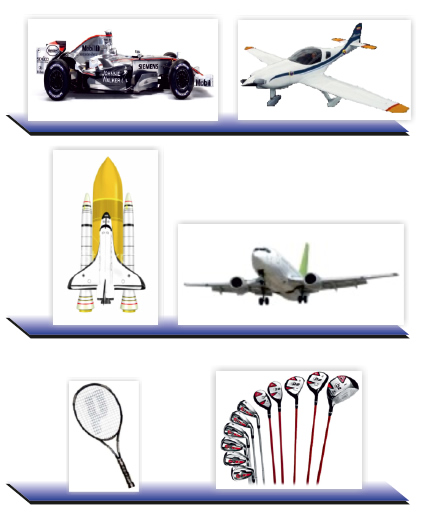
Figure 1. Applications of Composite Materials.
Colombia has not left behind the use of composite materials, neither. For decades, The Air Force has been working with composites structures in helicopters. Moreover, it is building its own trainer, the Calima T-90. It is a composites airplane made out of fiberglass, carbon fiber, and honeycomb. It has a total of 200 parts that are bonded using resin and hysol as adhesives.
So, even though composite materials reduce the number of parts in a structure, joining parts together is still needed. To do so, either bolts or adhesive can be used, or a combination of both (Gordon, 2005, 2006). However, using bolts means to create a hole on the composite part, which is a stress concentration factor that reduces its strength (Ko, 1985). Besides, weight is an important factor in aerospace applications and using bolts increases it.
Research shows that due to the stress concentrations caused by the fastener holes, the mechanical fastening can only achieve a maximum tensile strength of 50% of the weakest adherents in the joint, while the adhesively bonded joints can achieve about 80% of the tensile strength of the weakest adherents (Adams, 1989). As a result, adhesively bonded joints are popular in different industries (Cagle, 1968; Albericci, 1983; Kinloch, 1997; Adams, Comyn & Wake, 1997; Mays & Hutchinson, 1992; Sadek, 1987). However, statistics have shown that 70% of failures in structures initiates in the joints (Renton & Vinson, 1975). Hence, to ensure safety on structures, it is necessary to analyze and improve joint design.
1.1. Adhesively Bonded Joints
There are different ways in which components can be adhesively bonded. The parts to be bonded are usually denoted as adherents. Figure 2 shows the most common adhesively bonded joint configurations.
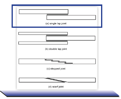
Figure 2. Adhesively Bonded Joints
Double lap join is a symmetric configuration where failure occurs due to shear stress. Stepped joint is a configuration created by a series of steps. The strength depends on the length and number of steps. This configuration allows having a smooth surface after bonding. However, geometric singularities are created at each step. On the other hand, scarf joint eliminates the singularities and still has same benefits as stepped joints. However, its manufacturing is very complex. Single lap joint is an asymmetric configuration; as a result, bending moment is produced on the adherents. Failure is produced by the peel stress at the geometric singularity. It is usually the most used type of joint because it is generally the simplest and least expensive to manufacture (Qian, 2008).
Some of the factors that affect the strength of joints are: Adhesive, surface preparation and bond line.
1.1.1. Adhesive
Joints can be bonded using either film or paste adhesive. Commercially available and used in aerospace sector film adhesives are: FM-73M and FM-94. On the other hand, the most common paste adhesive in the aerospace industry is the EA - 9394, hysol.
EA-9394 Hysol was used for this investigation. Researchers investigated the mechanical properties of EA- 9394 (Guess, Reedy, & Stavig, 1995; Kuhbander, 1994; Tomblin, Yan, & Harter, 2001). Guess et al. conducted mechanical tests for Hysol EA-9394 such as tension, compression, and fracture toughness, in 1995.
Hysol should be store in the freezer and its properties are guarantee for one year after the issue date. It is believe that after that period its properties would not change in high proportion if proper care has been taken with its storage. Hysol is a two component adhesive named part A and part B respectively. They should be mixed in a ratio 100 to 17; 100 of part A and 17 of part B. Prior to mixing they should be placed at room temperature for approximately 20 min so that the increase of temperature allows its manipulation.
1.1.2. Surface Preparation
Flinn et al. (2010) suggested that surface preparation is one of the most determinant factors of an adhesively bonded joint. They argue that one of the requirements for a good adhesion is that the adhesive should wet the adherent, and it depends on the surface energy. They made some experiments where they measured the contact angle of drops of several fluids and calculated the surface energy of the adherent. It showed that the contact angle is time dependent and that there is a relation between the contact angle and the surface after peel ply removal. They also stated that contaminants reduce the surface energy being necessary to clean well the surface prior bonding.
Surface treatment varies depending on the adherent. The idea is to create a rough surface for bonding and to remove any grease or contaminants. To avoid greasing the adherents by manipulation, gloves should be used at all time.
For composites adherents the surface treatment consist on initially wiping with acetone the adherents, then sanding with 110 grit sand paper, and finally wiping again removing any dust and grease left.
1.1.3. Bond Line
Qian (2011) showed that for asymmetric configuration of single lap joints the strength of the joint increases when decreasing the bond line thickness. He used spacers in order to generate different bond line thickness, and also manufactured and tested some specimens without the use of spacers. By doing so, he realized that the minimum bond line thickness that can be obtained using the bonding procedure was approximately 2 millimeters. Following his approach, no spacers were used during the present study.
The adhesive bond line is usually the weakest link in bonded joints. In addition the load transfer from one adherent to another occurs in a localized region. Hence, the load transfer has a relatively low efficiency. Moreover, highly concentrated interfacial stresses are present leading to premature failures and low joint strengths (Sun, 2004).
1.2. Improvement of Single Lap Joints
Researchers have worked on several ways to improve the efficiency of the single lap joints. Experimentally, Matthews and Tester investigated the effect of changing the stacking sequence in graphite/epoxy adherents on the joint strength of bonded single lap joints in 1985. The adherent considered consisted of 6, 8, and 10-ply varying overlap length from 0.5 to 1.0 inch. They found that the strength of single lap joints is definitely influenced by the lay-up and the stacking sequence of the composite adherents. Joint strength increased with proportion of 0° fibers and the greatest strength was obtained with the all 0° specimens. Also, strength increased with both 0° layers on the outside of the laminate. On the other hand, joint strength was unchanged with change of overlap if adherent strength is low.
Zeng and Sun proposed a new design of a wavy singlelap joint in 2001. The idea whit the wavy joint was to avoid eccentric load transfer and remove stress singularity at the end of the overlap. They showed that in contrast with the conventional single lap joint which has high tensional peel stresses at both joint ends, the wavy joint has compressive stresses near the joint ends. They verified the concept by experiment comparing joint strength to that of conventional single lap joint.
Coates and Armanios showed, in 2000, that the strength of the joint can be increased by increasing the number of planes that transfer load. In 2003, Turanga and Sun proposed a design of single lap joint with attachments for aluminum. Later, in 2008, they made a further study of their previous design using both composites and aluminum as adherent. They confirmed the idea that creating additional load transfer paths (attachments), the amount of load carried by the main lap region reduces, and so the interfacial stresses. They observed an increased of the joint strength of about 60%.
However, previous improved designs of single lap joint, with wavy geometries or attachments with angled surfaces, are very complicated to manufacture, making it expensive and time consuming for real life applications. The present study introduces a modification of previous research that will be easier to manufacture, in addition to improve the joint strength. The new design is shown in Figure 3.
The idea of splitting the connection with the other adherent was to be able to have a failsafe mechanism. It was expected that failure would occur initially in the first attachment, then in the second attachment, and finally on the main overlap region. So, the joint would be able to carry an amount of load before catastrophic failure happens, giving also some time to repair the structure.
2. Methodology
2.1. Specimen Fabrication
Three different kinds of joints were fabricated and tested: Single Lap Joint SLJ, Single Lap Join with Attachment-A SLJ-A and Single Lap Join with Attachment-B SLJA-B, as shown in Figure 3. The size of the autoclave in the composite material laboratory at Purdue University allowed curing panels of approximately 12in width by 48in long. During this project, usually 2 panels of 12x12 in were manufactured at a time. 10 specimens were obtained from those panels dimension. ASTM standards suggest having at least 7 specimens from the same bonded plate.
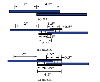
Figure 3. Joints Configuration for Design and Test.
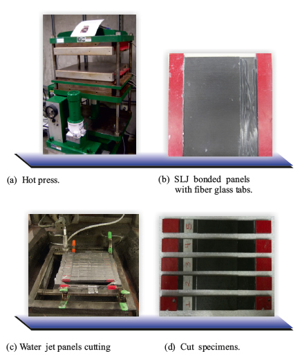
Figure 4. Specimen Manufacturing.
2.1.1. SLJ manufacturing
Single lap joint consists of two adherents that are bonded on the overlap region. IM7-8552 carbon fiber prepreg was used for the adherents.The stacking sequence chosen for the study was a [02 , 902 , 02 , 902 , 0]s . Panels were manufactured with the stacking sequence mentioned before using autoclave curing. After curing, panels were cut on the desired dimensions using water jet. Acetone was used to wipe the panels. Then, 110 grit sand paper was used to sand the bonded region. Acetone was used again to wipe the panels after sanding. Panels were put on the oven at 1500 F for 1 hour.
Panels were taken out from the oven and let at room temperature for 1 hour. A template with the panel dimensions and with the bonded region drawn was created and placed on an aluminum plate. Then, one of the panels was placed over the template with the designated bonded area dimensions to be use as a reference. Tabs were used in order to keep the level when applying pressure. Hysol was taken out from the freezer and let at room temperature for about 20min. The volume to be used was calculated with the bonded area and the desired bond line thickness. Approximately, 10% more of the total volume is prepared in order to account for the lost of adhesive during the application process. Each part was weighted in a scale separately and then mixed.
Hysol was applied on both faces to be bonded. After that, the second panel was placed over the initial lying on the template. Alignment of the panels with the template was verified. After that, a second aluminum plate was placed on the top of the set up. Carefully the whole arrangement was placed on the hot press and let under pressure for 45min, initially. This was done in order to remove the excess of adhesive. After 45min, it was released from pressure and all the excess of adhesive was cleaned with a spatula. After cleaning, bonded panels were put back in the hot press.
The hot press was used to apply a pressure of 2.8M P a. Pressure was applied for a period of 12 hours. Then, the bonded panels were released from pressure. For the first set of experiments of single lap joint, the excess of adhesive was removed. On the other hand, for the second set of SLJ experiments it was left in order to have an estimate of the effect of the fillet on the joint strength. Panels were put in an oven at a temperature of 1500F for 2 hours. Later, once the bonded panels were at room temperature, fiber glass tabs were bonded using a structural adhesive. Then, water jet was used to cut the bonded panels into single lap joint specimens. The specimens were 1 in wide. Specimens manufactured for the second set of SLJ can be seen on Figure 5.
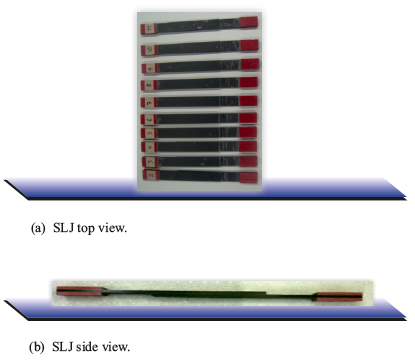
Figure 5. SLJ Specimens.
2.1.2. SLJA manufacturing
Single lap joint with attachment SLJA is a modification of the conventional single lap joint as shown in Figure 3.1. Attachments are incorporated in order to create a load path transfer, so that the peel stress at the singularity is reduced in comparison with SLJ. Because the idea is to compare the performance of SLJ versus SLJA, the total overlap length used was the same in both cases. The SLJA can be seen as an initially created SLJ with 1.5in overlap length to which attachments are added to create a total overlap length of 4.5in. An attachment is bonded at the top of each adherent and they are connected to the other adherent in two sections as shown in Figure 3 Two types of SLJA were manufactured and tested: SLJ A and SLJ B, as shown in Figure 3 (b) and Figure 3(c).
The adherents and the connector attachments on the SLJA were made out of I M 7-8552 and have the same stacking sequence to the SLJ, [02 , 902 , 03 , 902 , 0]s . The transfer load attachments were made out of S2 - 8552 with [±45]s.
Hysol was applied on each face to be bonded. The first components to be bonded were the connector attachments to the adherents, and the level tabs on the end of the adherent. Level tabs were obtained from the same panel that the adherent and the attachments in order to keep level to apply pressure. After that, one of the adherents with the tabs bonded to it was placed on the top of the other and aligned with the template on the corresponding bonded region. Then, the fiber glass connector attachment was bonded on the top of the bonded panels. It was then flipped over 1800 so that the other load transfer attachment could be bonded on the other side. Then, the same curing procedure was applied to SLJ was used for SLJA. After curing, water jet was used to obtain the specimens. No fillet was left for SLJA to reduce the scatter on the data, so that a comparison could be done between the conventional single lap joint, and the single lap joint with attachments.
2.2. Experimental Set Up
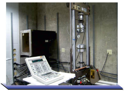
Figure 6. Experimental Set Up.
22 kip MTS machine, shown on Figure 6, was used for tension testing joint specimens. The MTS machine was connected to a data acquisition system from Labview. The load and displacement were recorded. Specimens were tested until failure at a rate of 0.02in/min.
3. Experimental Results
3.1. Single Lap Joint
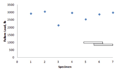
Figure 7. SLJA Experiment 1 (without fillet) Results
Two set of experiments were carried on with single lap joint. In the first experiment the excess of adhesive was removed, while in the second it was not and a fillet was created on both ends of the joint. Results from the single lap joint without fillet are shown in Figure 7. Adhesive failure was predominant on that set of specimens as shown in Figure 8. The correspondent failure modes of each specimen with its failure loads in pounds are shown in Table 1.
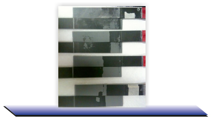
Figure 8. SLJ Failed Specimens Experiment 1 (without fillet).
Table 1. SLJ experiment 1 (without fillet) results
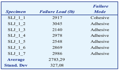
It is important to note that even though the specimen SLJ_1_1 had a cohesive failure mode, its failure load was not the highest from this set of experiments. On the other hand, the specimen with the highest failure load, failed in adhesive mode.
Failure mode and load results from the second experiment of single lap joint are shown in Table 2. Failure mode was mostly cohesive and even some of the specimens presented adherent failure as shown in Figure 10. It could be seen that some of the first layers of the adherent presented delamination. The highest failure loads were observed when adherent failure occurred.
Table 2. SLJ experiment 2 (with fillet) results
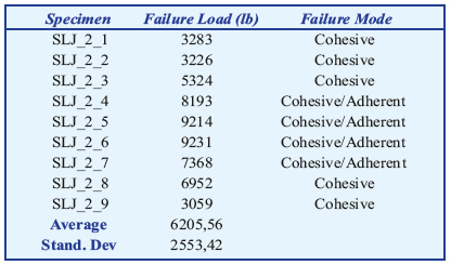
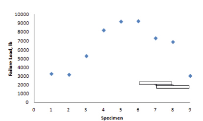
Figure 9. SLJ Experiment 2 (with fillet) Results.
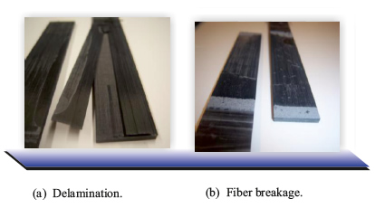
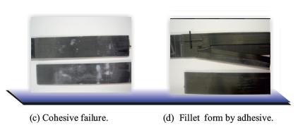
Figure 10. SLJ Failed Specimens Experiment 2 (with fillet).
Excess of adhesive was not completely removed in certain regions of the bonded panels during the curing process of the second experiment with SLJ. It was noticed that the specimens with the excess of adhesive along the whole edge had higher failure load that the specimens without adhesive along the edge. It was also true even for the specimens that were just partially cover with adhesive. As a result a huge scatter in the data was obtained as shown in Table 2. Results showed that the excess of adhesive has a bigger influence in the failure load than the surface preparation which at the end is reflected in either adhesive or cohesive failure.
3.2. Single Lap Joint with Attachments
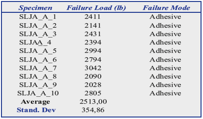
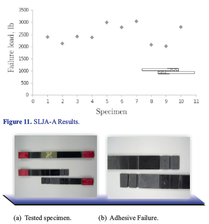
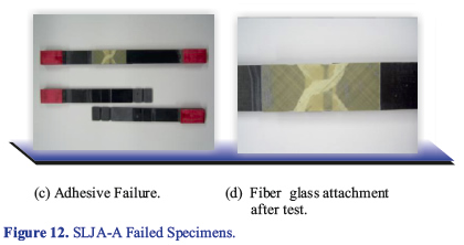
Results from the first experiment SLJA-A are shown on Table 3. Failed specimens can be seen on Figure 12. During the test, failure was explosive. All attachments failed at a rate that did not allow seeing a progressive failure. There was not delay between the failure of the first connector attachment and the others. Adhesive failure mode was considered to be responsible for the explosive failure.
It was considered that because of the small thickness of the load transfer attachment, and the imperfections of the hot press, the area used to calculate the pressure that should be applied to the bonded panels was being under estimated. As a result the input force in the hot press was smaller than it should be. Also, it was considered that the Hysol used for the experiment could be old and did not work properly.
Table 3. SLJA-A Experiment 1 Results
It was then decided to do an additional experiment where the length of the transfer load attachment covers the total overlap length of 4.5in, as shown in Figure 3 (c). This would allow to increase the area and to eliminate the uncertainty of the imperfections in the hot press and the applied pressure. Brand new Hysol was to be used for the second experiment.
Results from the second experiment are shown on Table 4 and Figure 13. Failed specimens can be seen on Figure 14. During the test, some of the specimens presented explosive failure and others presented failure in only one end of the bonded region.
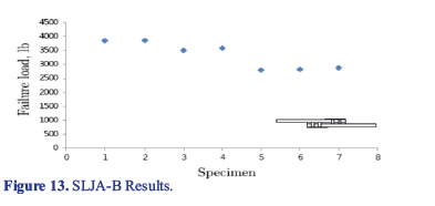
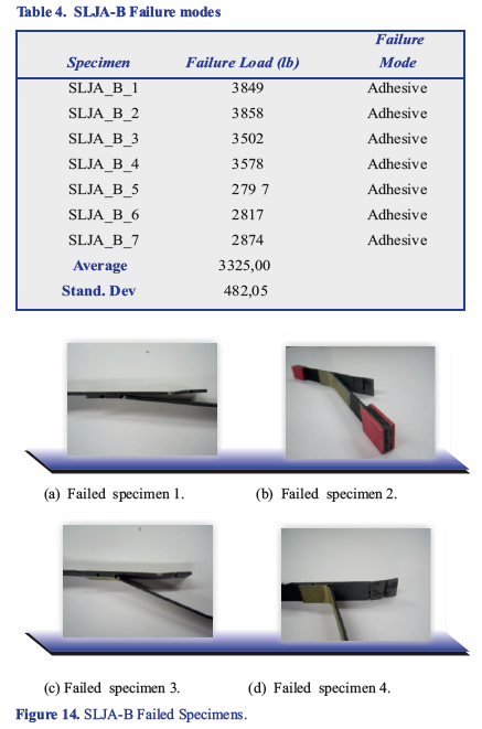
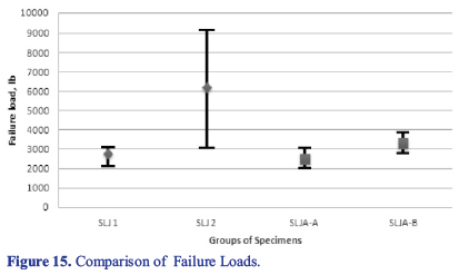
No excess of adhesive was left at the singularity, thus there was not fillet that could increase the strength. Despite the fact of using a new hysol, specimens failed in adhesive mode. The joint strength of the second experiment was higher than for the first experiment, but still after the initial failure, joints were to able to carry further load. Hence, failsafe mechanism was not achieved. Compiled results are shown in Figure 15.
4. Conclusions
An improvement on the joint strength of about 19% was achieved, considering SLJ 1 vs SLJA-B, taking into account that for both cases the excess of adhesive was removed. On the other hand, fillets created by the excess of adhesive in experiment 2 of SLJ increased the strength by 140%, comparing SLJ 1 vs SLJ 2.
There was a small variation on the joint strength when having adhesive failure in comparison with cohesive failure. On the other hand, when there was adherent failure due to the fillet, there was a large improvement on the joint strength. Further investigation should be done to investigate closely the relation between the portion of the edge cover by adhesive and the failure load.
Adhesive failure was presented during both experiments of Single lap joint with attachment. Explosive failure occurred on the first experiment and in most of the specimens from the second experiment of SLJA. No failure was presented on the fiber glass attachments. Some specimens from the second set failed in just one end. However, bearing load capability after the initial failure of those specimens was low. Thus, the hypothesis that creating joints with attachments on the configuration proposed in the present investigation would create a safe fail mechanism could not be confirmed. Further study is needed to achieve a joint with this feature.
References
Adams, R (1989). Strength Predictions for Lap Joints, Especially with Composite Adherends: A review. Journal of adhesion,30, pp.219-242.
Adams, R. D, Comyn, J. and Wake, W. C. (1997) Structural Adhesive Joints in Engineering, 2nd ed. London; New York: Chapman &Hall.
Albericci, P. (1983). Aerospace Applications in Durability of Structural adhesives. Edited by Kinloch, A. J., Applied Science Publishers.
ASTM D5868 (2008). Standard Test Method for Lap Shear Adhesion for Fiber Reinforced Plastic (FRP) bonding. AST Mannual book of standards.
Cagle, C. V. (1968). Adhesive Bonding: Techniques and Applications. New York: McGraw-Hill.
Chung, D. (2010). Composite Materials: Science and Applications. New York: Springer.
Coates, C. W., & Armanios, E. A. (2000). An Assessment of Nested Overlap and Transverse Interfacial Layer in Co-Cured Composite Single Lap Joints. American Society for Composites. Dayton, OH.
Flinn, B., Ohuchi, F., Phariss, M., Satterwhite, J., Au-bin, J., & Keenen, C. (2010). Improving Adhesive Bonding of Composites through Surface Characterization, The Joint Advanced Materials and Structures Center of Excellence, CECAM, and AMTAS, University of Washington in: http://depts.washington.edu/amtas/ev-ents/ jams_ 08/21.Flinn.pdf
Gordon, K. (2005). Load Transfer in Hybrid (Bonded/Bolted) Composite Single-Lap Joints. Composite Structures, 69, pp.35–43.
Gordon, K. (2006). Quasi-Static Strength and Fatigue Life of Hybrid (bonded/bolted) composite single-lap joints. Composite Structures, 72:119–129.
Guess, T. R., Reedy, E. D.,.& Stavig, M. E. (1995). Mechanical properties of hysol ea-9394 structural adhesive. Technical Report SAND95-0229, Sandia National Laboratories.
Kinloch, A. J. (1997). Adhesives in Engineering, Proceedings of the Institution of Mechanical Engineers. Part G, Journal of Aerospace Engineering, 211, pp.307-335.
Ko, W, (1985). Stress Concentration Factor Around A Small Circular Hole In The Himat Composite Plate. NASA Technical memorandum 86038.
Kuhbander, R. (1994). Characterization of ea9394 Adhesive for Repair Applications. Technical Report WL-TR-92-4069, University of Dayton.
Matthews, F.L., & Tester, T.T. (1985). The Influence of Stacking Sequence on the Strength of bonded CFRP single lap joints. International Journal of Adhesion and Adhesives, 5(1), pp.13–18.
Mays, G. C. and Hutchinson, A. R. (1992). Adhesives in Civil Engineering, Cambridge University Press, Cambridge.
Qian, H. (2008). A Study of Failure in Bonded Lap Joints Using Fracture Mechanics. PhD thesis, Purdue University.
Qing, Z., & Sun, C. T, (2001). Novel Design of a Bonded Lap Joint. AIAA Journal, 39(10), pp. 1991–1996.
Renton, W. J., & Vinson, J. R. (1975). The Efficient Design of Adhesive Bonded Joints, Journal of Adhesion, 7, 1975, pp.175–193. doi:10.1080/00218467508075049
Roh, H. S.(2011). Repairs of Composite Structures. Ph.D. thesis, Purdue University
Sadek, M. M. (1987), Industrial Applications of Adhesive Bonding. London; New York: Elsevier Applied Science
Sun, C.T. (2004). Design of Efficient Bonded Joints for Thin Walled Composites Structures. Proceedings for The Joint American Society Of Composites / American Society for Testing and Materials Committee D30 - Nineteenth Technical Conference, Atlanta, GA.
Tomblin, J.S., Yang, C. & Harter, P. (2001). Investigation of thick bondline adhesive joints. Final Report DOT/FAA/AR-01/33, Wichita State University
Turaga, U.V.R.S. & Sun, C. T. (2003). An investigation of Adhesively single-lap joints with attachments. 44rd AIAA/ASME/ASCE/AHS/ACS Structures, Structural Dynamics, and Materials Conference. Norfolk, Va
Turaga, U.V.R.S. & Sun, C. T. (2008). An Improved Design for Metallic and Composite Single-Lap Joints. AIAA Journal of Aircraft, 45(2), pp. 440–447.
Zhuguo, Z., Yingchun, Z., & Xupo, O. (2011). Study on Key Certification Issues of Composite Airframe Structures for Commercial Transport Airplane. Procedia Engineering, 17, pp. 247-257.